555 Logic Diagram

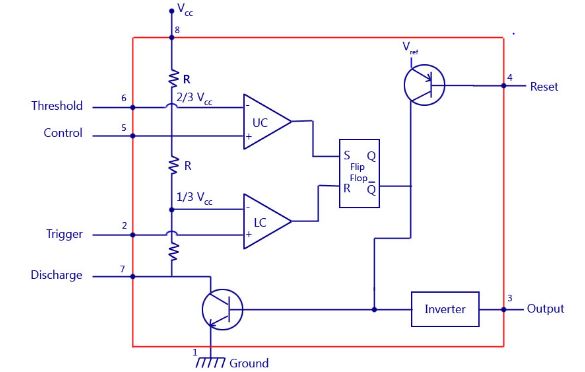
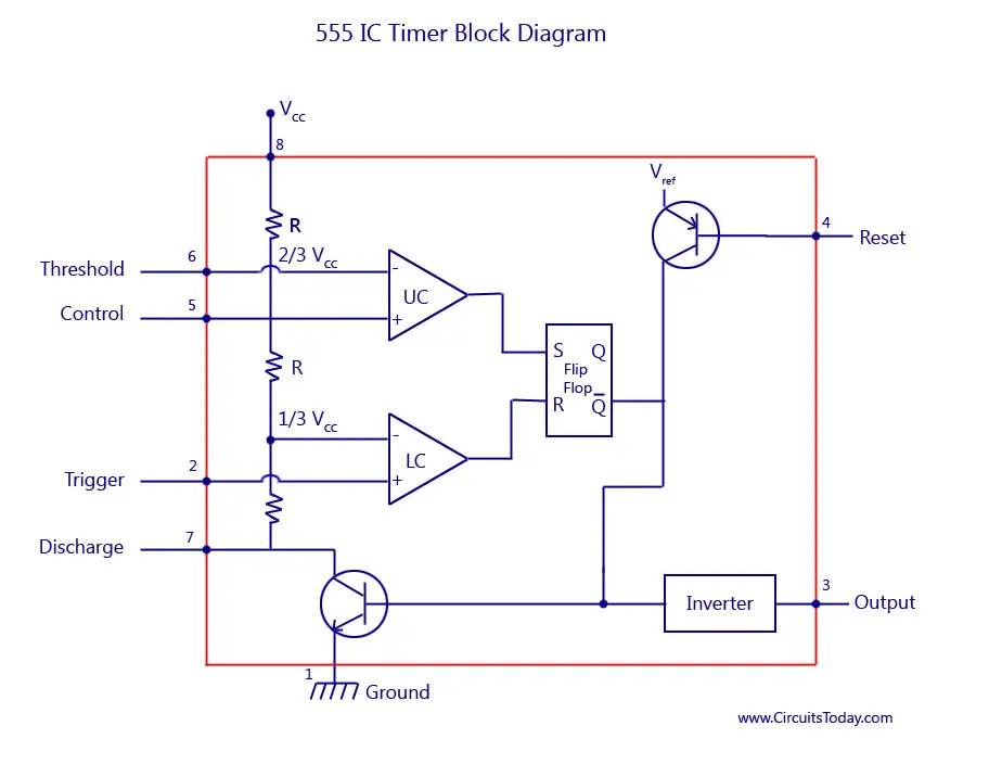
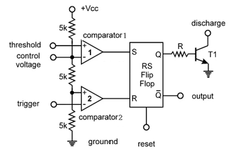
Internal block diagram the 555 timer ic is an integrated circuit chip used in a variety of timer pulse generation and oscillator applications.
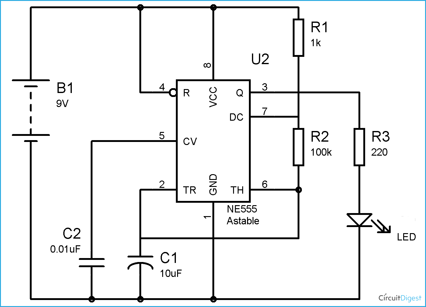
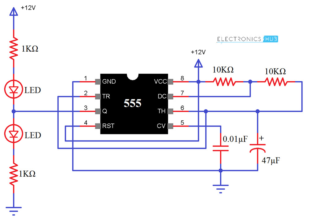
555 logic diagram. It is combining analog and digital chip. The following diagrams show some unusual circuits for the lm555 timer. 555 timer block diagram. This is a pulse generator circuits or standard astable multivibrator oscillator or free running circuit using ic555 timerne555lm555 we use it for digital logic circuits.
Overall these circuits demonstrate the flexibility of the 555 and 556 timer integrated circuits. As you would probably think it took me a very long time to make this but it. In monostable mode the duration for. I do not take credit for these schematics they were made by collin mitchel.
There are a lot of applications of this ic mostly used as vibrators like astable multivibrator monostable multivibrator and bistable multivibrator. It is a affordable stable and user friendly ic in application such as monostable and bi stable. These are a whole bunch of things to make with the 555 timer ic with a note for each picture. 47 projects to do with a 555.
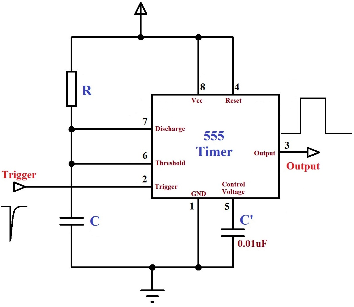
All we need to change the value of resistor r1 andor capacitor c1. These circuits were developed to provide certain functions that are not typically associated with this device. We can use this property of 555 timer to create various timer circuits like 1 minute timer circuit 5 minute timer circuit 10 minute timer circuit 15 minute timer circuit etc. 555 timer was first introduced by signetics corporation in 1971 as se555ne555.
You can find here some circuits based on 5555 ic. Ic 555 is popular easy to use small size with 8 pins. We need to set 555 timer in monostable mode to build timer. This tutorial covers different aspects of 555 timer ic and explains its working in.
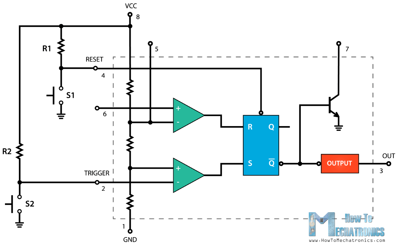
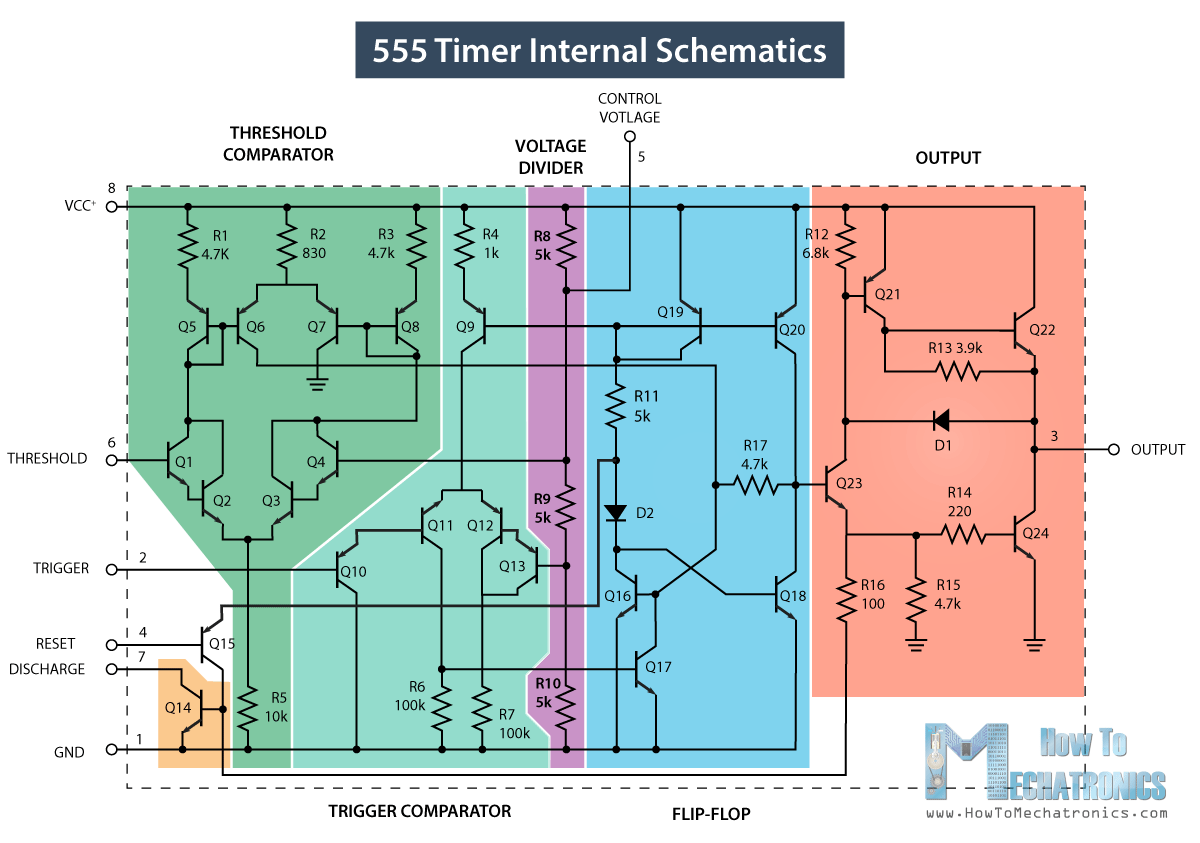
A 555 timer has two comparators which are basically 2 op amps an r s flip flop two transistors and a resistive network. Here is the list of 40 555 timer circuits that can help you in understanding 555 timer functionsfirst five circuits explains about 555 timer and its different modes. The block diagram of a 555 timer is shown in the above figure. The 555 timer uses several transistors to construct its comparators see the image notes in fig 3 so in the simplified functional diagram in fig 2 they are represented by boxes labelled comparator.
Derivatives provide two 556 or four 558 timing circuits in one package. A simplified block diagram representing the internal circuitry of the 555 timer is given below with a brief explanation of each of its connecting pins to help provide a clearer understanding of how it works.
