Wiring Diagram For Pertronix Ignition

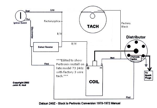
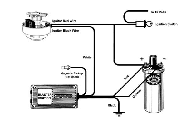
The pertronix ignitor needs 12v to its red wire and a ground to its black wire.
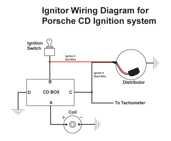
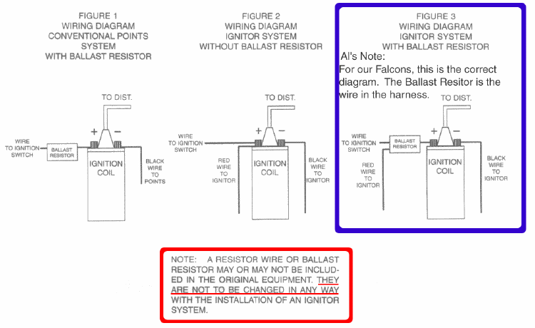
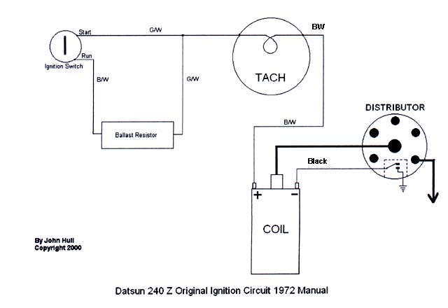
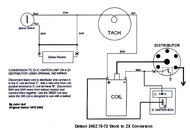
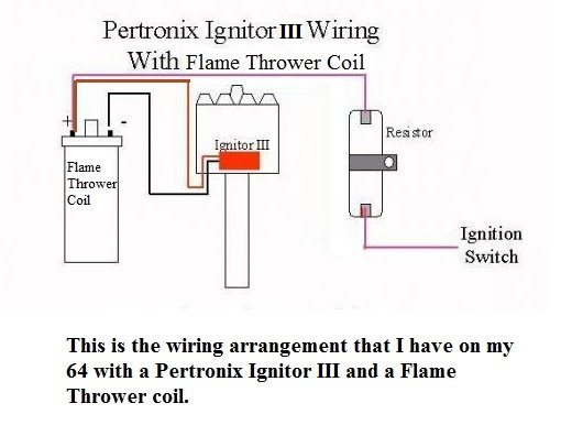
Wiring diagram for pertronix ignition. Ignitor common questions and answers figure 1 wiring diagram conventional points system with ballast resistor figure 2 wiring diagram ignitor system without ballast resistor figure 3 wiring diagram ignitor system with ballast resistor note. If not the arrangement will not function as it ought to be. Do you mean a nominal 15 ohm coil with a ballasted wiring loom or a 30 ohm coil for any year wiring loom with or without a ballast wire in the loom or an external eg. 914world msdpertronix installation and regarding pertronix ignition wiring diagram image size 720 x 540 px and to view image details please click the image.
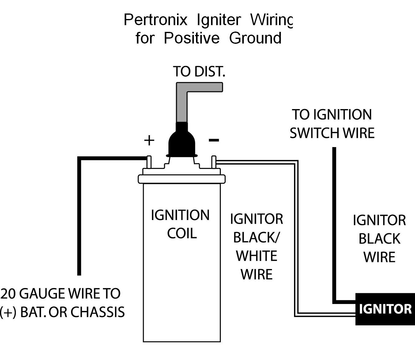
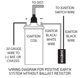
Pertronix ignitor wiring diagram pertronix ignition wiring diagram pertronix ignitor ii wiring diagram pertronix ignitor iii wiring diagram every electrical arrangement is made up of various different components. It goes without saying that this is valid only for cars without ballast resistors viz our t series cars. Here is a picture gallery about pertronix ignition wiring diagram complete with the description of the image please find the image you need. Pertronix igniter wiring for positive ground cars.
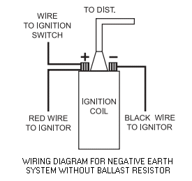
It shows the wire running from the alternator regulator to the positive side of the coil along with the red wire from the module and the wire from the ignition ballast being removed. The wiring diagram shown below is modeled after one obtained from pertronix. The wiring diagram shown below was obtained from pertronix to show the proper hookup for a pertronix igniter in a car wired for positive ground or earth if you prefer. Pertronix igniter wiring for negative ground cars.
Each component ought to be placed and linked to different parts in particular manner. It goes without saying that this is valid only for cars without ballast resistors viz our t series cars.
