Step Down Chopper Diagram

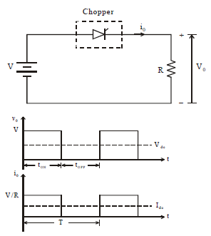
A when thyristor is on supply voltage appears across the load a when thyristor is off the voltage across the load will be zero.
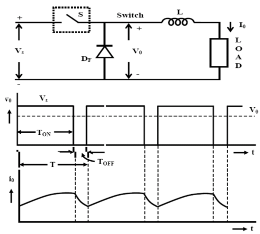
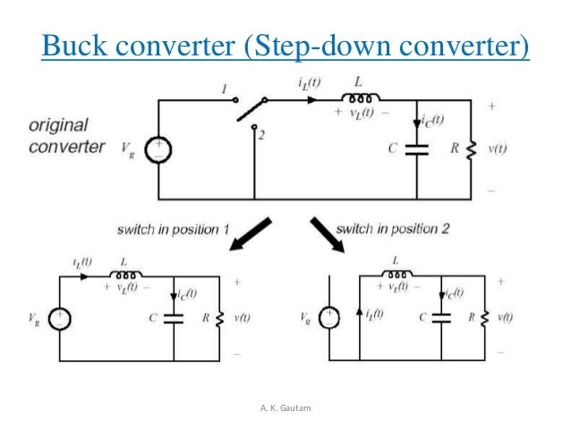
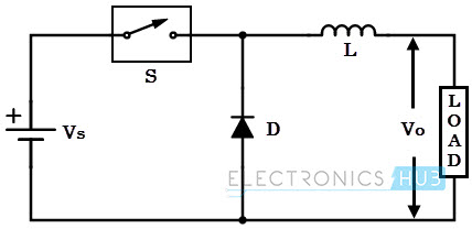
Step down chopper diagram. Step up and step down choppers with diagrams are also described. In the previous articles we have seen basic operation and principle of a chopperin this tutorial we will see principle of step down chopper buck converter with a neat sketch of circuit diagram. When ch is turned on v s directly appears across the load as shown in figure. Step up step down chopper.
Step down chopper for r load. It makes it possible to increase or reduce the voltage input level. So v o v s. Step down chopper as buck converted is used to reduce the ip voltage level at the output side.
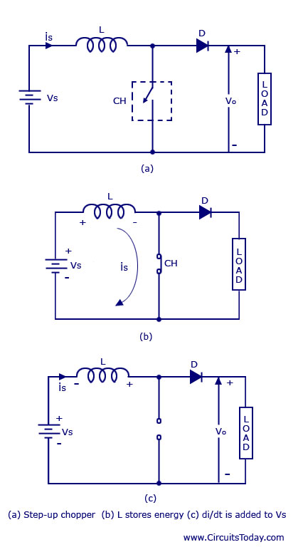
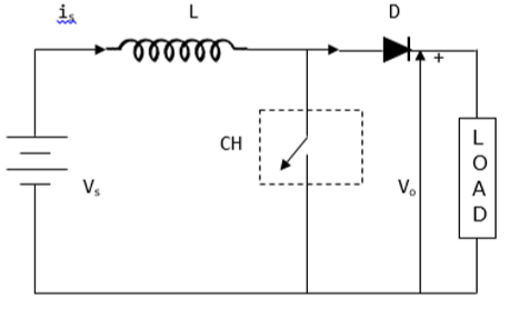
Choppers and its types ac and dc choppers explained with chopper circuit diagrams. In the circuit a large inductor l is connected in series to the supply voltage. Circuit diagram of a step down chopper is shown in the adjacent figure. The diagram below shows a buck boost chopper.
A the thyristor in the circuit acts as a switch. This chopper is used when the output dc voltage has to be made higher than the input voltage. Step up chopper works as a step up transformer on dc current. This is also known as a buck boost converter.
The working principle of a step up chopper can be explained from the above diagram. V 0 or the average output voltage is less than the input voltage v s so this type of chopper is called a. For a step down chopper the voltage output is always less than the voltage input.
