Motor Starter Circuit Diagram

Ac Motor Control Circuits Worksheet Ac Electric Circuits
Basic Wiring For Motor Control Technical Data Guide Eep
Basic Wiring For Motor Control Technical Data Guide Eep
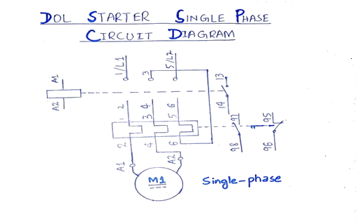
In the below dol starter wiring diagram i shown a molded case circuit breaker a magnetic contactor normally open push button normally close push button switch thermal overload relay motor trip indicator and 3 phase motor.
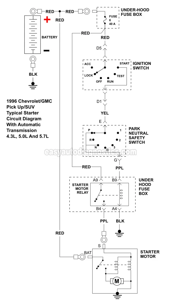
Motor starter circuit diagram. Lever mounted on the front of the switch. A typical starter solenoid has one small connector for the starter control wire the white connector in the photo and two large terminals. Three phase motor power control wiring diagrams three phase motor connection schematic power and control wiring installation diagrams. All diagrams are intended to illustrate the logic of a latching contol circuit.
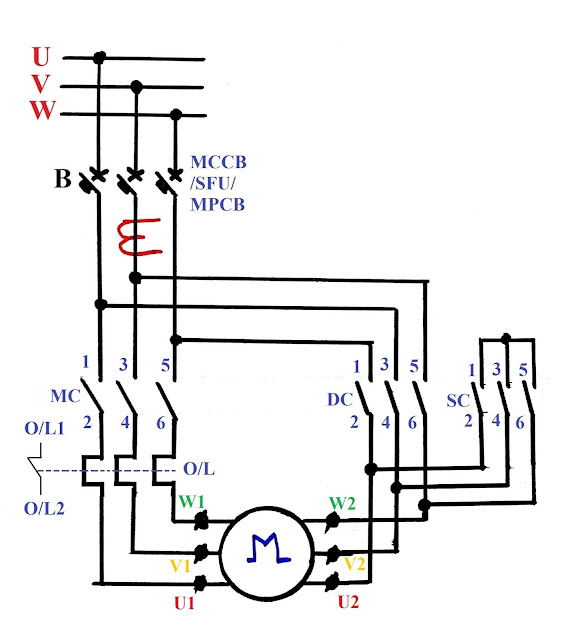
Wiring diagrams do not show the operating mechanism since it is not electrically controlled. They show the relative location of the components. Four point manual dc motor starter circuit diagram. One wiring called main wiring which is used for motor.
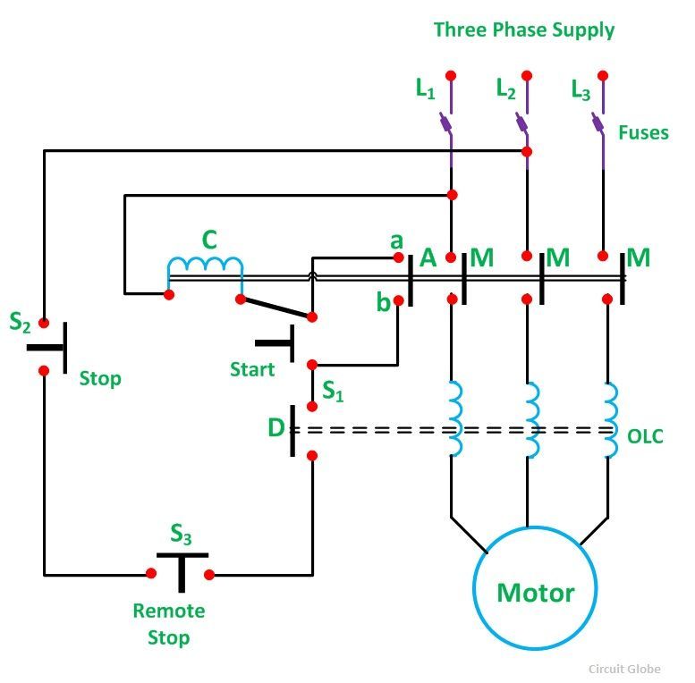
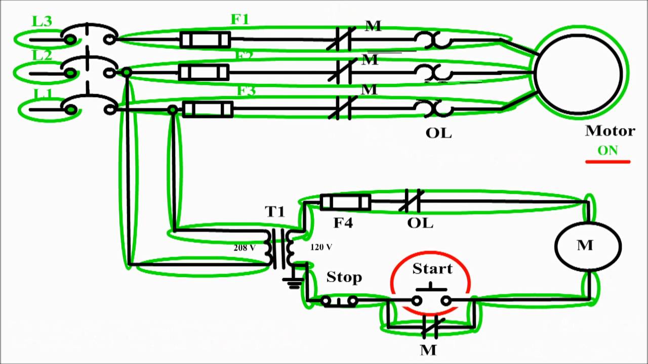
Figure 1 typical wiring diagram. Starters are also known as contactors and are usually labeled with the letter m in ladder diagrams. And one wiring is called controlling wiring. The specific circuit needs to be respectively learned referring to different typical control circuits.
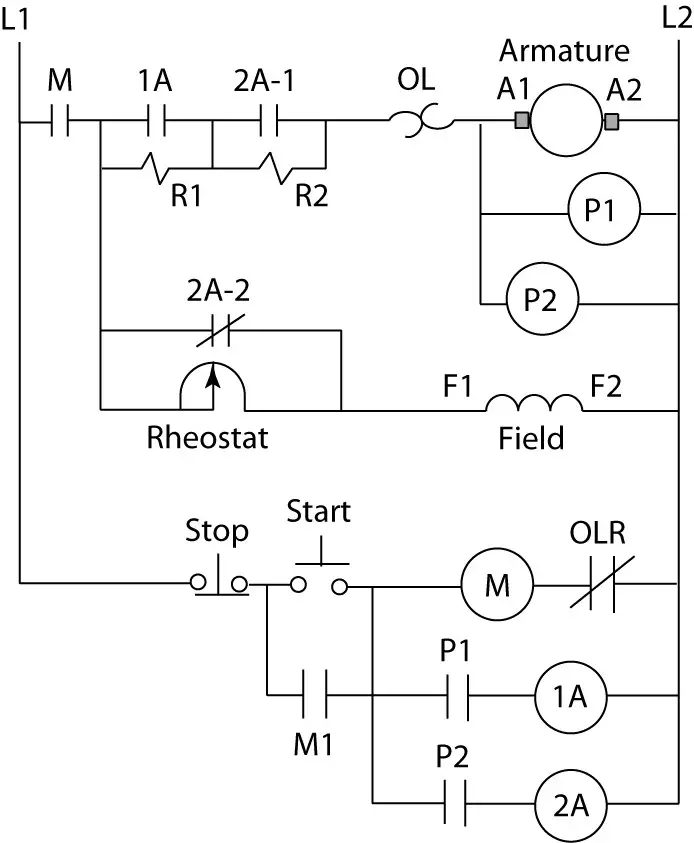
Figure 1 is a typical wiring diagram for a three phase magnetic motor starter. An automatic starter operates in a similar fashion except that automatic relays short out sections of the starter resistance either by a time sequence or when the armature current drops to a selected value. These motor starters consist of an on off snap switch combined with a thermal overload device operating on the eutectic alloy ratchet principle. The typical starting system wiring diagrams can divide into non relay control type single starter relay control type and security starter relay control type.
An alternative current motor is capable of self starting because of the relationship between the flux of. A starter is another name for the large power relay used to conduct current to the motor lines. Star delta y d 3 phase motor starting method by automatic star delta starter with timer. Basic wiring for motor control technical data.
Figure 4 shows the automatic dc starter circuit diagram. The starter solenoid works as a powerful electric relay. Your motor starter may use wiring which is internal to the starter wiring which is different than the diagrams etc. If you are not sure of how to make the connections on your equipment hire an electrician.
Then we shall move towards the circuit diagram of soft starters for induction motors. Ask your students to identify any motor control circuit diagrams theyve already seen as being across the line. One for the positive battery cable and the other for the thick wire that powers the starter motor itself see the diagram below. They can be used as a guide when wiring the controller.
What Is Direct On Line Starter Its Theory Of Starting
Ac Motor Control Circuits Worksheet Ac Electric Circuits

Ac Motor Control Circuits Worksheet Ac Electric Circuits

Current Limit Dc Motor Starter Circuit Diagram Electrical

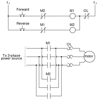
Forward And Reverse Motor Starter Wiring Diagram Elec Eng
Two Wire Three Wire Motor Control Circuit Motor Control
What Is Direct Online Starter Dol Working Principle

Ac Motor Control Circuits Worksheet Ac Electric Circuits

2 Wire Control Circuit Diagram Motor Control Basics Controlling Three Phase Motor
Counter Emf Dc Motor Starter Circuit Diagram Electrical

Motor Control Circuits Types Electrical Industrial
Automatic Star Delta Motor Starter Electrical Technology

Direct Online Starter Dol Starter Diagram Circuit Diagram
Motor Control Circuit Diagram Start Stop 3 Wire Control

Direct Online Starter Or Dol Motor Starter Electrical

Sequence Controls For Motor Starters

Motor Control Circuits Types Electrical Industrial
Start Stop Jog Circuit Motor Control Circuit Diagram
