Logic Gate Wiring Diagram
Digital Electronics Logic Gates Basics Tutorial Circuit

Logic And Gate Tutorial With Logic And Gate Truth Table

Or Gate Circuit Diagram Using Ic 74ls32
Gates circuits and boolean algebra.
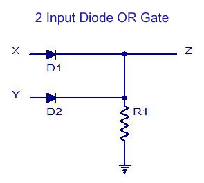
Logic gate wiring diagram. The reason for which the computers are capable of performing complex operation is due to the interconnection of these logic gates. As you can see as long as any one of the inputs is 1 the output will be 1 and only if all inputs are 0 will the result be 0. June 15 2018 february 24 2012 by electrical4u. Due to this reason logic gates can also be considered as electronic circuits.
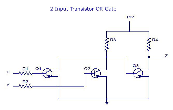
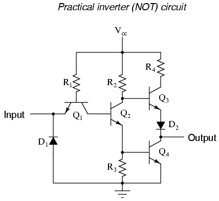
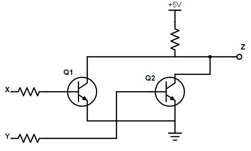
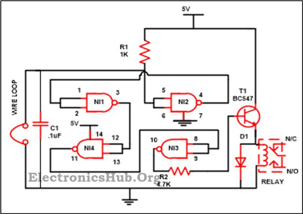
One of them is a wiring diagram which is a comprehensive diagram of each electrical circuit system showing all the connectors wiring terminal boards signal connections buses between the devices and electrical or electronic components of the circuit and it also identifies the wires by wire numbers or colour coding. One of them is a wiring diagram which is a comprehensive diagram of each electrical circuit system showing all the connectors wiring terminal boards signal connections buses between the devices and electrical or electronic components of the circuit and it also identifies the wires by wire numbers or colour coding. In electronics a not gate is more commonly called an inverter. The circuit diagram of transistor logic gate is shown below.
The circuit symbol is that arrowhead kind of shape and inputs and outputs are marked the same way as the and gate. Another type of logic gate is the or gate. This gate is mainly used in applications where there is a need for mathematical calculations. Constructing gates a transistor is a device that acts depending on the voltage level of an input signal either as a wire that conducts electricity or as a resistor that blocks the flow of electricity.
And logic gate is a digital logic gate designed for arithmetic and logical operations every electronic student must have studied this gate is hisher career. On a circuit diagram it must be accompanied by a statement asserting that the positive logic convention or negative logic convention is being. Logic diagrams truth tables. So in calculators computers and manly digital applications use this gate.
Logic gates are implemented by using transistors diodes relays optics and molecules or even by several mechanical elements. The circle on the symbol is called a bubble and is used in logic diagrams to indicate a logic negation between the external logic state and the internal logic state 1 to 0 or vice versa. One of them is a wiring diagram which is a comprehensive diagram of each electrical circuit system showing all the connectors wiring terminal boards signal connections buses between the devices and electrical or electronic components of the circuit and it also identifies the wires by wire numbers or colour coding.

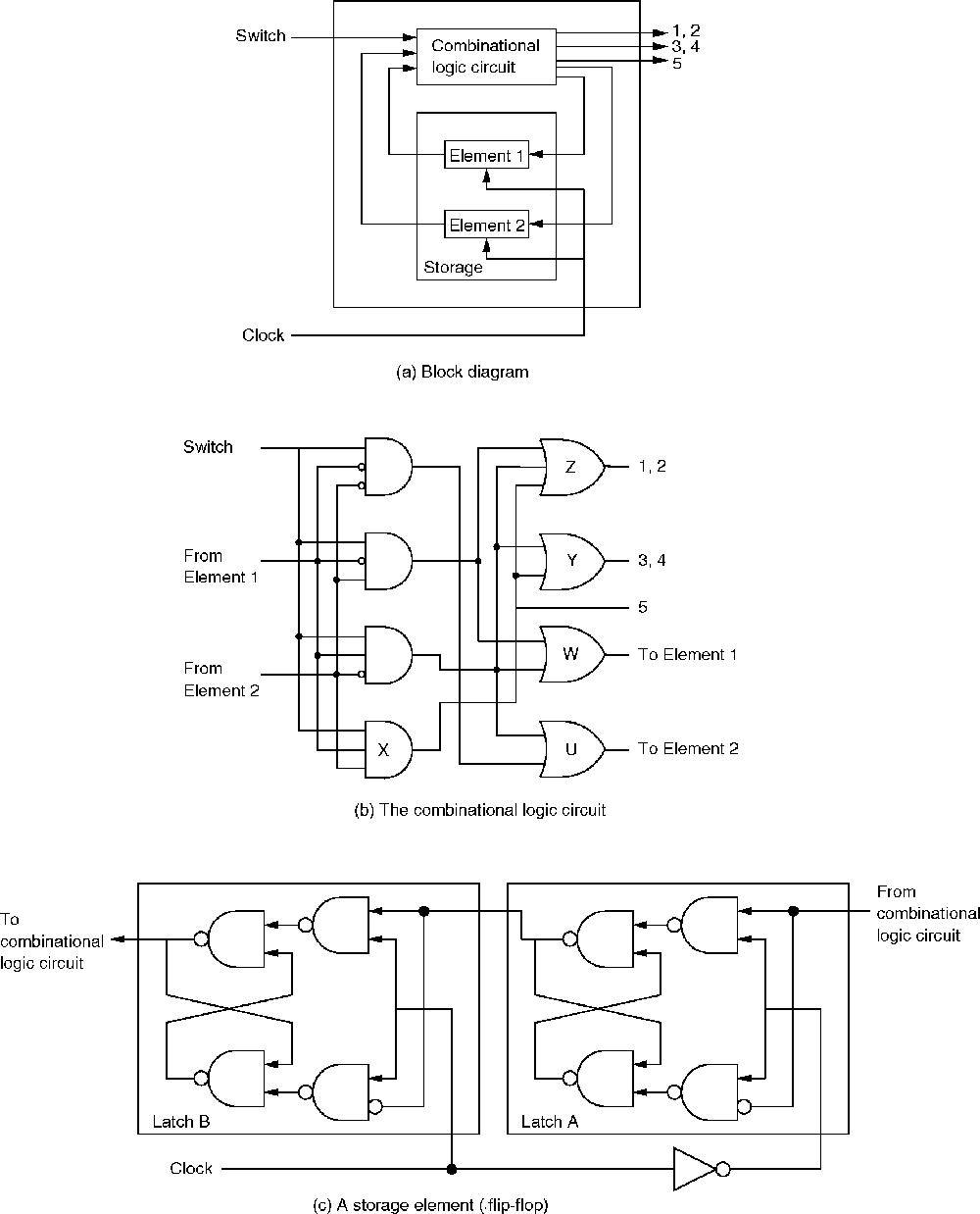
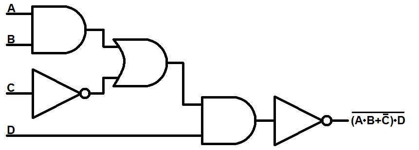
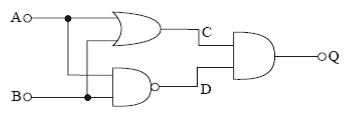
Combinational Logic Circuits Using Logic Gates

Combinational Circuit Logic Gate Diagram
Digital Electronics Logic Gates Basics Tutorial Circuit
Lessons In Electric Circuits Volume Iv Digital Chapter 3

Full Adder Logic Gate Circuit Diagram Template Logic
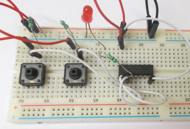
And Gate Circuit Diagram Working Explanation
Logicblocks Digital Logic Introduction Learn Sparkfun Com

3 Logic Circuits Boolean Algebra And Truth Tables Dr

Controlling A Calculator Display With Logic Gates Logic

Digital Logic Gate Tutorial Basic Logic Gates
Introduction To Logic Gates Not And Nand Or Nor
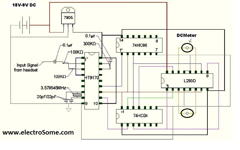
Cell Phone Controlled Land Rover Using Logic Gates
Digital Electronics And Logic Circuits Role Of Transistors
Luggage Security Alarm Project Circuit Using Logic Gates

Interfacing Logic Circuits With Host Physiology A The

Logic Circuits Computer Science Gcse Guru

The Not Gate Logic Gates Electronics Textbook
Computer Science
