Learning Wiring Schematic

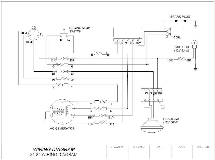
Some wire colors are specific to the wires use such as black white red and green while others are used for component connection and change function from one circuit to another.
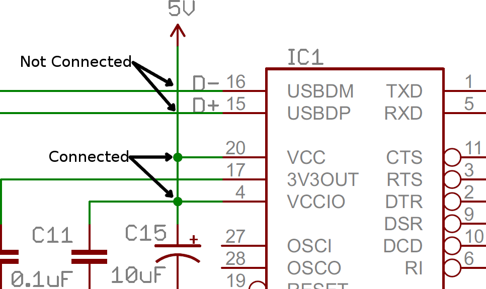
Learning wiring schematic. And its not that hard at all. If they do not connect one will be shown looping around the other in a semicircle. Learn to read electrical and electronic circuit diagrams or schematics. This comprehensive interactive multimedia training program consists of two individual lessons that train participants to read and interpret wiring diagrams single line diagrams building electrical diagrams and ladder diagrams.
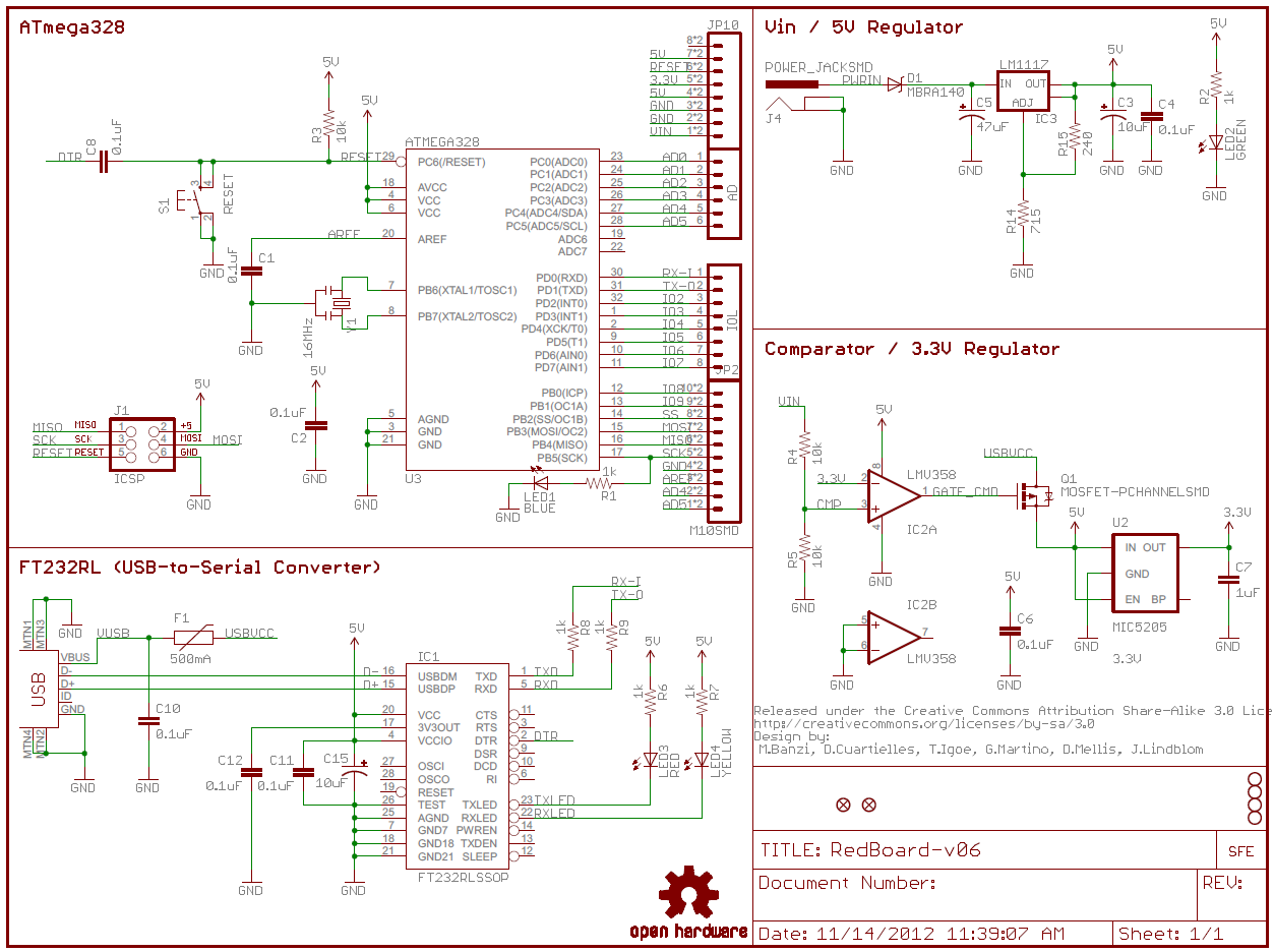
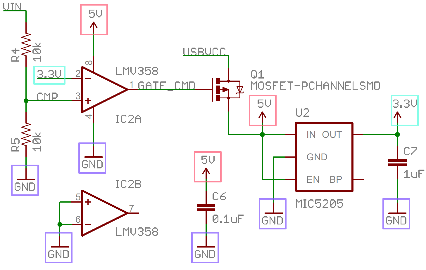
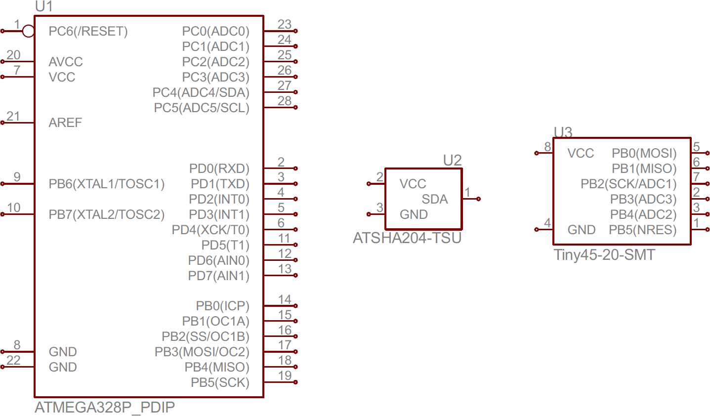
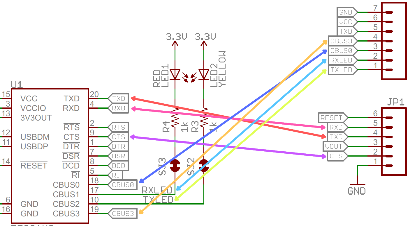
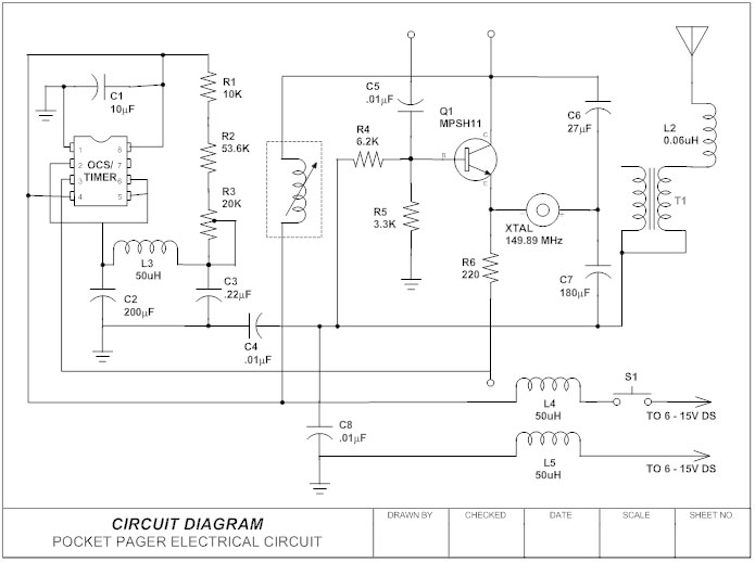
Learning to read car wiring diagrams is an awesome skill to add to your auto mechanic skillset. A drawing of an electrical or electronic circuit is known as a circuit diagram but can also be called a schematic diagram or just schematic. Circuit or schematic diagrams consist of symbols representing physical components and lines representing wires or electrical conductors. Wires may cross each other on a schematic but that does not necessarily mean that they connect.
Potentiometers and variable resistors. Schematics wiring diagrams is part five of the motor controls eight part training series. Resistors on a schematic are usually represented by a few zig zag lines with two terminals extending outward. Wires are used to connect the devices together.
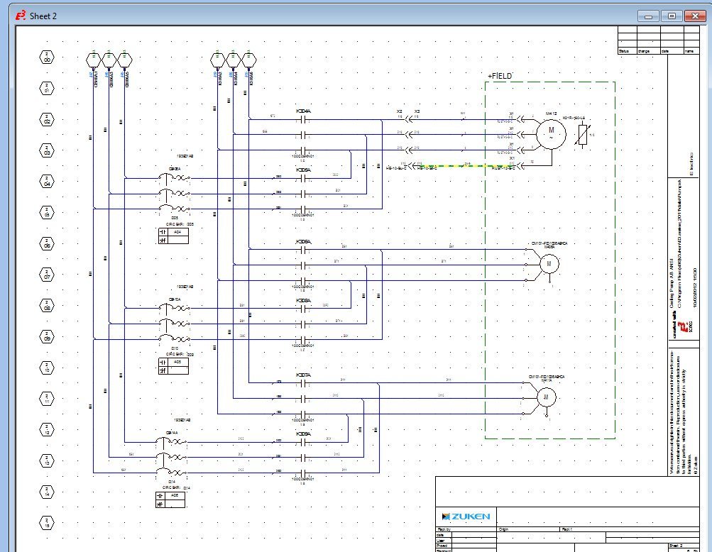
Schematics and wiring diagrams are the written language of control circuits. Wire diagrams use wire color codes to identify the color of wire being used to connect different electrical components within the circuit. Before a technician can become proficient in troubleshooting control circuits he must learn how to read and interpret schematic and wiring diagrams. Being able to master this competency will not only help you find solutions to common electrical problems a lot faster but will also give you a big headstart compared to less qualified technicians.
