Control4 Dimmer Wiring Diagram

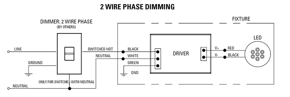
Black line red switched hot grey neutral.
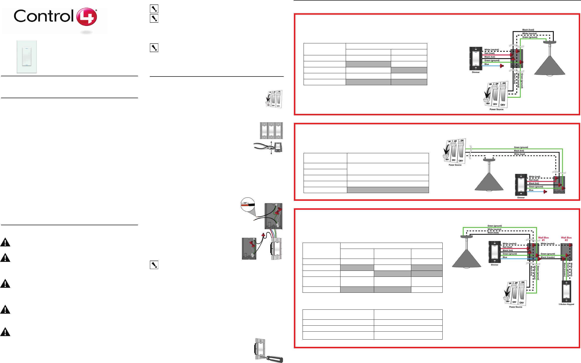
Control4 dimmer wiring diagram. Wireless switch installation guide. Wiring in control4 panel wiring diagrams use the control4 8 channel 0 10v dimmer wiring diagrams along with the 8 channel 0 10v dimmer installation guide to install 8 channel 0 10v dimmers. It installs in a standard wall box using conventional wiring standards and communicates with other devices through a wireless rf radio frequency connection. C4 dim1 z wireless dimmer specifications and supported fixtures this control4 wireless dimmer operates as part of a control4 home automation system to enable intelligent lighting control.
C4 din 0 10v dim e 8 channel dimmer 8 channel 0 10v dimmer wiring guide figure 1. This control4 wireless dimmer operates as part of a control4 home automation system to enable intelligent lighting control. 8 channel dimmer wiring guide diagrams color code. Box contents adaptive phase dimmer wire.
It installs in a standard back box using typical wiring. C4 apd277 adaptive phase dimmer 277v introduction the control4 adaptive phase dimmer operates independently or as part of a control4 home automation system. Control4 dimmer wiring diagram wiring diagram is a simplified customary pictorial representation of an electrical circuit. Ground wire to make a secure connection to the safety ground of the electrical system.
Wire nuts according to the relevant wiring diagram. Wiring in control4 panel wiring diagrams use the control4 8 channel dimmer wiring diagrams along with the 8 channel dimmer installation guide to install 8 channel dimmers. It shows the components of the circuit as simplified shapes and the gift and signal contacts in the company of the devices. Black line red load grey neutral green earth ground blue ethernet figure 1.


