Block Diagram Of 565 Pll
The dc level is then passed on to a vco.
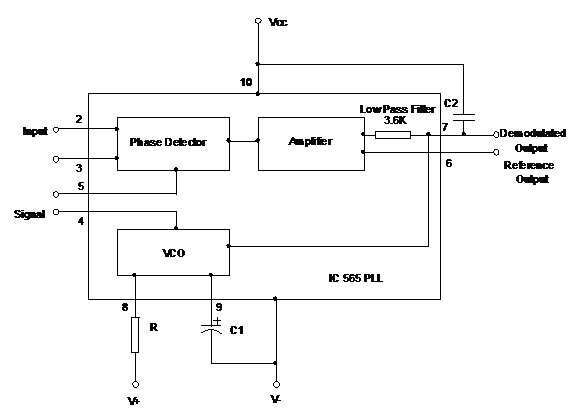
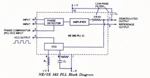
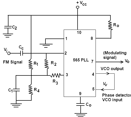
Block diagram of 565 pll. The output frequency of the vco fo is directly proportional to the input signal. It consists of figure b shows the block diagram of ic 565 phase detector. There are several different types. Figure 1 shows the block diagram of phase locked loop.
The simplest is an electronic circuit consisting of a variable frequency oscillator and a phase detector in a feedback loop. The block diagram of ic 565 pll consists of phase detector amplifier low pass filter and vco. Ic 565 is the most commonly used phase locked loop ic. The pll forms the basis of a number of rf systems including the indirect frequency synthesizer a form of fm demodulator and it enables the recovery of a stable continuous carrier from a pulse waveform.
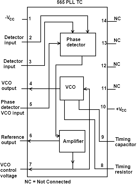
30 lecciones de dibujo del creador de akiko espacio de diseno de mark crilley en formato pdf o epub. 30 lecciones de dibujo del creador de akiko espacio de diseno aproveche esta oportunidad unica de convertir tus. The internal block diagram shows that ic 565 pll consists of phase detector vco and amplifier. Phase locked loop operation.
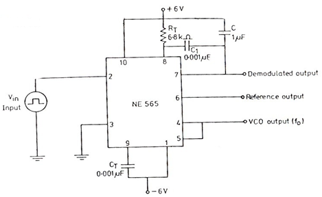
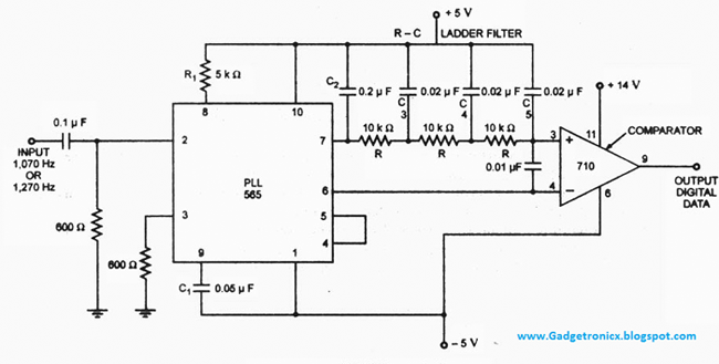
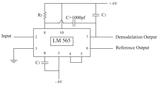
What is phase locked loop. Therefore it is necessary to connect output of vco pin 4 to the phase comparator input pin 5 externally. The amplifier also functions as the low pass filter. Block diagram and working principle of pll the phase locked loop consists of a phase detector a voltage controlled oscillator and in between them a low pass filter is fixed.
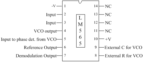
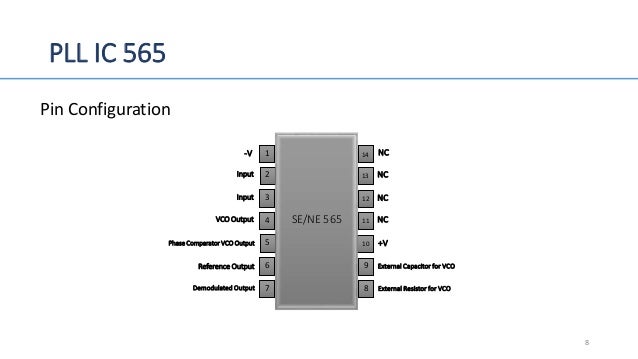
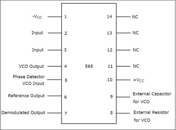
Thus the pll works in these stages free running capture and phase lock. The input signal vi with an input frequency fi is conceded by a phase detector. What is the need of it and how it works. The pin diagram of ic 565 is shown in the following figure the purpose of each pin is self explanatory from the above diagram.
1 the phase detector compares the input frequency fin with the feedback frequency fout. Enter image description here phase detector. Both the input frequency and output frequency are compared and adjusted through feedback loops until the output frequency equals the input frequency. Rahsoft radio frequency certificate 41057 views.
It is a 14 pin dual inline package dip. Puedes leer cualquier libro en linea o. The phase locked loop pll is a very useful building block particularly for radio frequency applications. As shown in the block diagram the phase locked feedback loop is not internally connected.
Block diagram of 565 pll block diagram of 565 pll obtenga el libro de dominar el manga. Now it is said to be pll is operating in the lock mode. A phase locked loop or phase lock loop pll is a control system that generates an output signal whose phase is related to the phase of an input signal.

